Electrolytic Cell Titanium Electrode Supplier · China

Custom Electrolytic Cells Engineered Around Your Electrodes, Flow and Power

We design each custom electrolysis cell from your reaction, electrolyte and current data, then build the titanium electrodes, chamber, flow path and connections as one matched assembly. You validate one system from one factory instead of coordinating four vendors.

Have process data or a drawing? Start with a free engineering review.

ElectrodesMMO, Ir-Ta or Pt anodes and Ti cathodes matched to your reaction
FlowInlet, distribution and outlet sized to your flow rate
PowerBusbars and terminals rated for your operating current
InterfacesPorts, sensors and mounts that fit your existing skid

R&D, production and export under one roof · ~100 employees · Shipping to 7 countries · Samples from 1–10 pieces · OEM / ODM

Electrolytic Cell Components

Five Layers That Decide How Your Electrolytic Cell Performs

We review every project in this order, so each electrolytic cell component is specified against the reaction it serves rather than copied from a catalogue. Gaps found early cost a phone call; gaps found after delivery cost a rebuild.

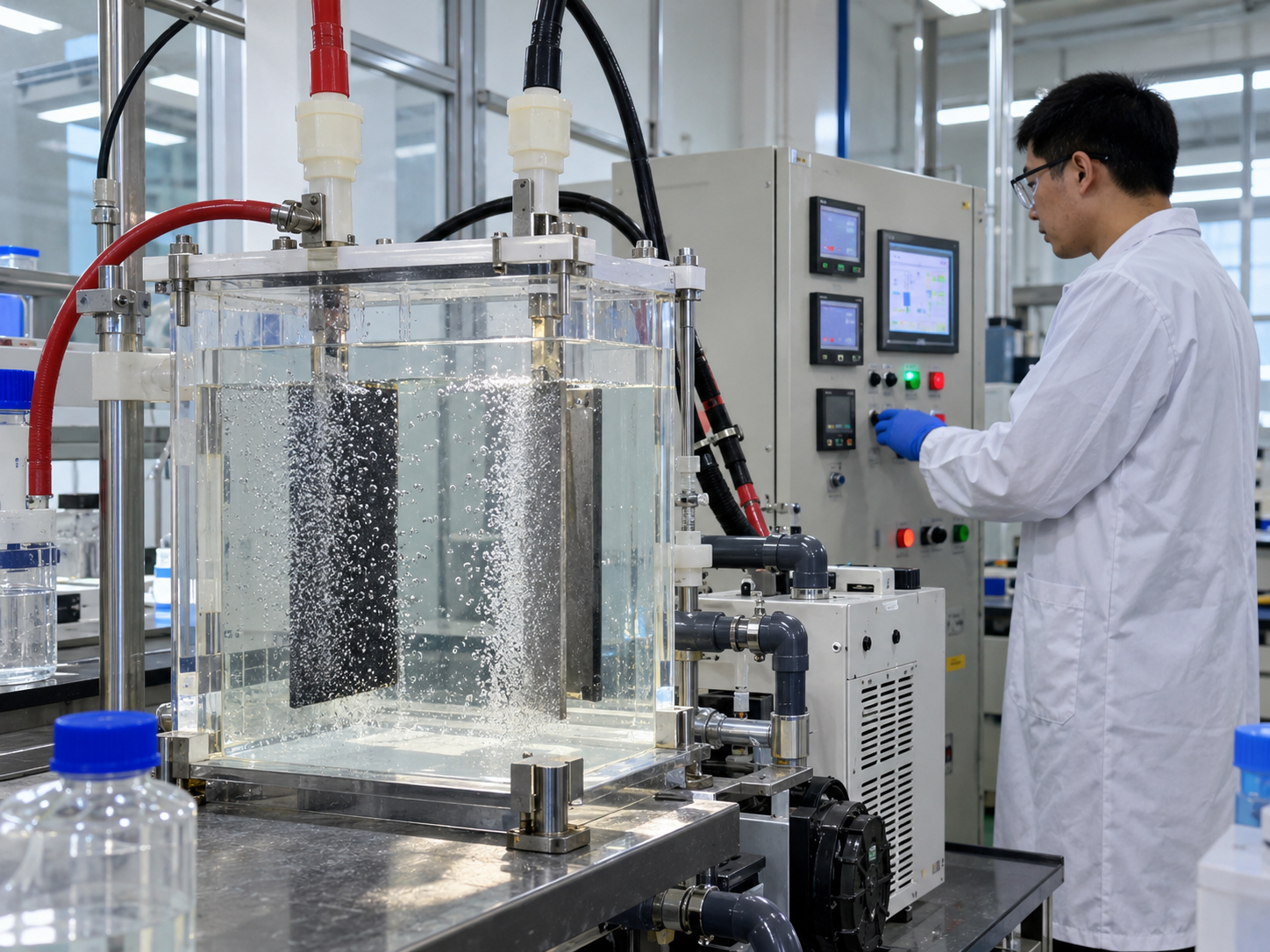
Laboratory electrolysis test cells used to define the target reaction
Layer 01

Process and Target Reaction

We start from what the cell must produce, remove or recover, plus your electrolyte and output target. Coating, gap and materials are then selected from data, which prevents early coating failure.

Defines → electrode choice
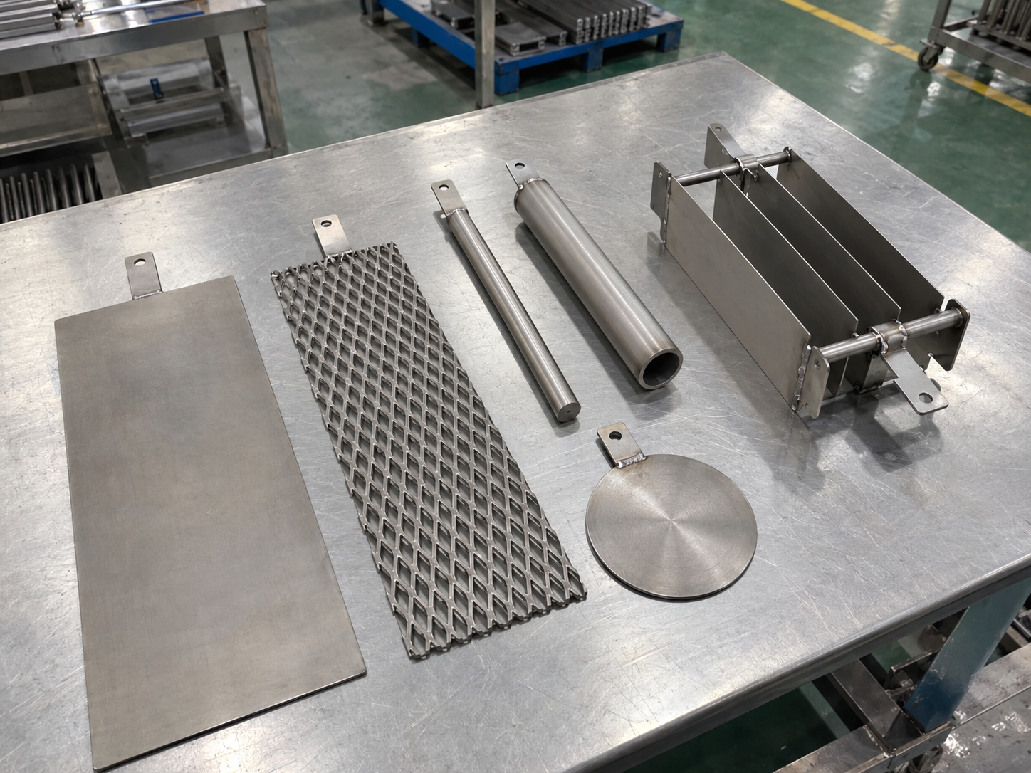
Titanium plate, mesh, rod, tube and disc electrodes for electrolytic cells
Layer 02

Anode, Cathode and Electrode Arrangement

Titanium electrodes for electrolytic cells are matched by coating, geometry and spacing, giving you a predictable cell voltage and even current distribution across the plate.

Defines → chamber size
Electrolytic cell body with stacked electrode chambers
Layer 03

Cell Body, Chambers and Interfaces

Chambers, seals and port positions are drawn around your electrode pack, so the body fits your skid and stays leak-tight at real operating pressure and temperature.

Defines → flow path
Electrolysis skid with liquid flow piping and gas separation
Layer 04

Liquid Flow, Gas Release and Maintenance

Flow and gas outlets are placed to clear bubbles and deposits from the electrode zone, which keeps efficiency stable and stretches your cleaning interval.

Defines → power layout
Copper busbar and terminal connections on an electrolytic cell
Layer 05

Power Connections, Monitoring and Control

Busbars, terminals and sensor ports are sized to your current, cutting contact heat and giving your control system the readings it needs to run unattended.

Closes the loop → validation

Not sure which layer is missing data? We will mark the gaps for you.

Send Your Process Data →
Start From Your Process

Choose What Your Cell Must Do, and See What We Will Ask First

Each process goal raises different electrode, flow and interface questions. Answering them before quotation shortens design rounds and stops you from comparing offers built on different assumptions.

Electrolytic cell generating gas bubbles on titanium electrodes

Generate a Chemical or Gas

Chlorine, hypochlorite, oxygen, hydrogen or oxidants: output depends on how fast gas leaves the electrode and how well the coating suits the evolution reaction.

Electrodes

Chlorine- or oxygen-evolution coating chosen for your electrolyte and current density.

Flow

A gas-liquid path that clears bubbles before they raise cell voltage.

Interfaces

Gas outlet, venting and product sampling points placed for safe operation.

You get stable output per kWh and a coating life you can schedule maintenance around.
Electrochemical reactor treating contaminated wastewater

Remove or Transform a Contaminant

COD, ammonia, cyanide or organics: removal rate depends on contact time, anode potential and how chloride in your water changes the reaction path.

Electrodes

High-potential anodes such as Ir-Ta or Pt assessed against your pollutant and chloride level.

Flow

Residence time and mixing sized to your actual load, not a generic rate.

Interfaces

Pre-filtration, pH control and treated-water discharge points.

You confirm removal on your own water in a sample cell before committing to full scale.
Copper cathodes lifted from electrowinning cells for metal recovery

Recover a Metal or Resource

Copper, nickel, precious metals or other resources: deposit quality depends on even current distribution and easy cathode handling.

Electrodes

Dimensionally stable titanium anodes paired with cathodes you can strip or replace.

Flow

Uniform electrolyte distribution for consistent deposit thickness.

Interfaces

Cathode lifting, harvest access and contact bar alignment.

You get cleaner deposits and avoid the lead contamination and anode sludge of lead-alloy anodes.
Membrane stack for electrodialysis ion separation

Separate Ions or Streams

Electrodialysis, descaling or membrane cells: the end electrodes must survive polarity reversal and mixed chemistries while the stack stays sealed.

Electrodes

End-electrode coatings rated for polarity reversal and mixed chloride and oxygen duty.

Flow

Separate dilute and concentrate channels with controlled cross-leakage.

Interfaces

Stack compression, manifolds, spacers and membrane seating.

You get a cleaner product stream and fewer shutdowns caused by scaling on the electrodes.
On-site water disinfection electrolysis unit with dosing piping

Treat or Disinfect Water

Pools, drinking water, cooling towers or process water: dose stability depends on the anode coating, salt level and how scale is managed on the cathode.

Electrodes

Ru-Ir MMO anodes sized for your chlorine output, with reversal cleaning where needed.

Flow

Brine or inline flow designed to limit scale build-up on the cathode.

Interfaces

Dosing, flow switch and hydrogen venting into your treatment line.

You disinfect on site without storing chlorine, with a dose your controller can hold steady.

An application name is only a starting point. Electrolyte, current density, temperature and duty cycle decide the actual design.

Tell us your goal and electrolyte, and we will return the questions that matter.

Discuss Your Process Goal →
Exploded Cell Architecture

Six Subsystems, One Accountable Electrode Manufacturer

We split every custom electrolytic cell into six subsystems and engineer the boundaries between them, because that is where most leaks, hot spots and early failures begin. Because we coat the electrodes ourselves, those boundaries are designed by the same team.

Exploded view of a titanium electrode assembly with plates and conductor 123 456 Exploded electrode pack · layout varies by project
1

Electrode Subsystem

Anodes and cathodes cut, formed and coated in our own plant, so coating loading and geometry match your current density.

2

Mechanical Support and Spacing

Insulating spacers, guides and clamps hold the electrode gap in tolerance, keeping voltage consistent across the whole plate.

3

Cell Body and Chamber Interfaces

Body material is chosen for your chemistry and temperature, with chambers and seals drawn around the electrode pack.

4

Hydraulic and Gas Subsystem

Inlets, distributors, outlets and gas ports keep the electrode zone flooded and free of trapped gas pockets.

5

Electrical Connection Subsystem

Titanium-clad copper or solid titanium conductors and terminals sized to your current, keeping contact resistance and heat low.

6

Service and Replacement Access

Removable electrode packs and standard fasteners let your team inspect, clean or swap electrodes without rebuilding the cell.

Want this breakdown applied to your own cell? Send a sketch, even a rough one.

Get a Subsystem Review →
Flow and Residence Path

Follow the Electrolyte Through Your Cell, Frame by Frame

An electrode only performs as well as the liquid around it. We plan the full path from inlet to drain, so concentration, gas and deposits stay under control and your coating wears evenly.

01 / 06Inlet piping and flow distribution to an electrolysis cell

Inlet and Distribution

Headers and distributors spread flow across the full electrode width, so no zone of coating works harder than the rest.

02 / 06Electrolyte flowing through transparent electrode tanks

Electrode-Zone Flow

Gap velocity is set to refresh electrolyte at the surface, which holds current efficiency as concentration drops.

03 / 06Transparent test cell showing electrolyte residence around electrodes

Residence and Mixing

Chamber volume and baffles give the reaction the contact time it needs to reach your target in one pass or a defined loop.

04 / 06Electrolytic cell with gas release and separation zone

Gas Release or Separation

Gas leaves upward through dedicated ports, reducing bubble blanketing that would otherwise raise voltage and energy cost.

05 / 06Product outlet and recirculation loop on an electrolysis skid

Product Outlet or Recirculation

Outlet position and loop design match your tank and pump, making product concentration easy to control and sample.

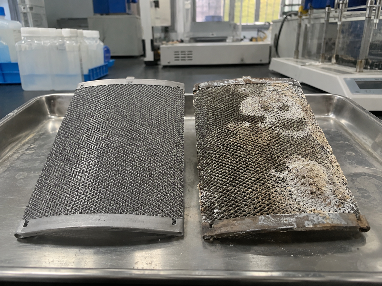
06 / 06Clean titanium mesh electrode next to a scaled electrode after service

Drain, Cleaning and Maintenance

Low-point drains and acid-cleaning access let you remove scale quickly, protecting coating life between services.

Flow layouts are based on your measured rates and engineering calculation. We do not present unverified simulation images as performance results.

Share your flow rate and tank layout, and we will propose the path.

Plan My Cell Flow Path →
Electrical · Thermal · Gas

Three Engineering Sheets We Size Together, Not One at a Time

Current, heat and gas are linked inside every electrolysis cell. We work through all three on your actual operating window, so the cell holds its rated output on the hottest day and at the highest load.

ElectricalSHEET E-01
DC power supplies testing an electrolysis cell current path

Current Path

  • Current densitySet per coating type and duty cycle
  • Voltage windowChecked against your rectifier rating
  • ConnectionsTi-clad copper, bolted or welded terminals
  • BusbarsCross-section sized to total current
  • PolarityFixed or reversing, defined up front

Even current keeps coating wear uniform and stops contacts from overheating.

ThermalSHEET T-02
Electrolytic cell stack with temperature monitoring in operation

Heat Balance

  • Electrolyte temp.Normal and start-up conditions
  • Peak conditionHighest load at highest ambient
  • Heat removalFlow, cooling coil or heat exchanger
  • Material limitsBody, seals and membranes rated to peak
  • SensorsTemperature points at hottest zone

Controlled temperature protects coating life and keeps seals from creeping.

GasSHEET G-03
Gas separation vessels connected to an electrolysis system

Gas Handling

  • Expected gasChlorine, oxygen, hydrogen or mixed
  • OutletPort size and height for full release
  • SeparationGas-liquid separation before discharge
  • VentilationInterface to your exhaust or dilution
  • MonitoringLevel, flow or gas detector points

Fast gas removal lowers cell voltage and keeps hydrogen handling safe.

Send your current, temperature and gas data, and we will check the balance.

Check My Operating Window →
System Integration Interfaces

Every Connection Around Your Cell, Defined Before Fabrication

Most installation delays come from interfaces nobody owned: a port on the wrong side, a busbar that does not reach, a sensor with no thread. We draw all six interface groups around your cell, so it drops into your skid on the first fit.

STEP 1

Process Equipment Interface

Matched to your tanks, pumps, filters and dosing units, with agreed connection standards.

STEP 2

Piping: Inlet, Outlet, Drain, Recirculation

Port sizes, flange or thread types and orientation fixed on the drawing you approve.

STEP 3

Rectifier, Cable and Busbar

Terminal position, bolt size and current rating aligned with your power supply.

Electrolytic cell installed in a skid with piping, power and sensor connections Your Electrolytic Cell
STEP 4

Sensors, Sampling and Monitoring

Ports for temperature, level, pH, ORP or gas detection placed where readings are meaningful.

STEP 5

Mechanical Frame and Mounting

Mounting points, footprint and lifting lugs drawn to your frame and floor space.

STEP 6

Cleaning, Disassembly and Replacement

Access for acid cleaning and electrode swaps without disconnecting the whole system.

Send a photo or drawing of your skid, and we will map the interfaces for you.

Map My Cell Interfaces →
One Architecture, Many Processes

Where Our Cell Architecture Is Applied, and What Changes Each Time

The same five layers apply everywhere, but the reaction, medium, electrode and validation change by application. Pick yours to see the engineering points that matter for your industry.

Custom Electrolytic Cell ArchitectureProcess · Electrodes · Body · Flow and Gas · Power

Your application not listed? Describe the reaction, and we will assess it.

Describe My Application →
Inputs · Cell · Outputs

What Goes In, What We Build, What You Get Out

A quotation is only as accurate as the data behind it. This diagram shows the inputs we need and the outputs we design for, so you can compare suppliers on the same basis and avoid redesign after the order.

Inputs

From you
  • Electrolyte composition, pH, chloride and impurities
  • Flow rate, pressure and batch or continuous mode
  • Temperature normal and peak range
  • Current total amps or target current density
  • Voltage rectifier rating and limits
  • Gas expected type and handling assumptions
→
Assembled electrolytic cell stack under test on a workbench

Electrolytic Cell

Built by ARY
Electrodes Spacing Chambers Interfaces Connections Controls
→

Outputs

Designed for
  • Product stream concentration and quality
  • Concentrate or reject stream handling
  • Gas volume, outlet and venting route
  • Deposits metal harvest or scale removal
  • Heat generated and how it is removed
  • Test data voltage, current and output records
DrawingYour sketch, 2D or 3D file in any common format
QuantitySamples from 1–10 pieces, then pilot and volume
DeliveryTarget date, destination and Incoterms
NDASigned before you share sensitive drawings

Missing a few inputs? Send what you have, and we will help fill the rest.

Submit My Inputs →
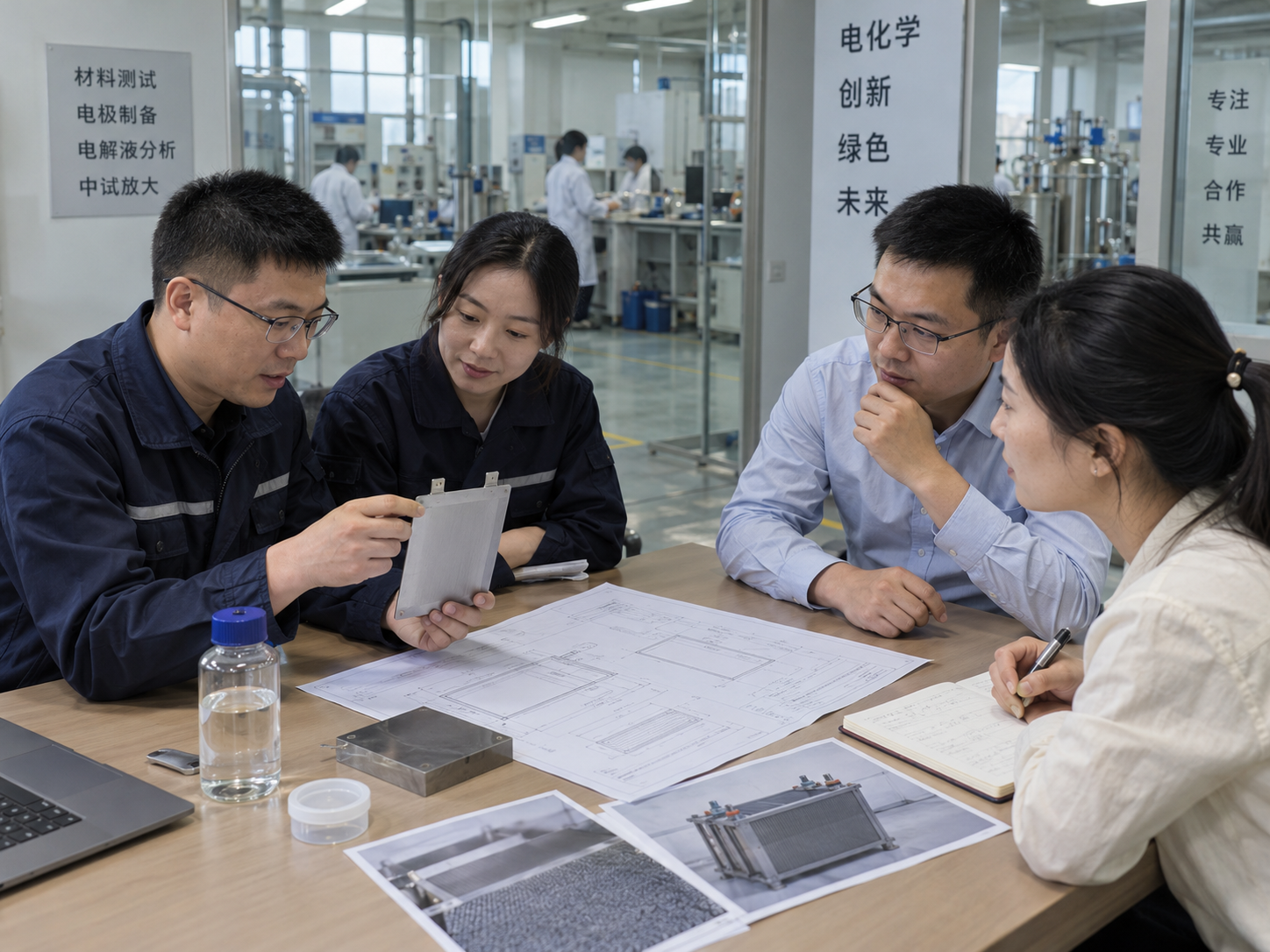
Engineering, quality and purchasing teams reviewing electrolytic cell drawings
Engineering Collaboration

Five Teams, Five Stages, and a Clear Owner for Every Task

Your engineers, buyers and quality staff each know exactly what they owe and what they receive at every stage. That keeps the project moving from first data to repeat orders without lost emails or surprise requirements.

YOU Customer responsibilityARY Our responsibility
Team / Stage
Stage 1Project Data and Missing Questions
Stage 2Process and Electrode Definition
Stage 3Mechanical Drawing and Interfaces
Stage 4Sample Build and Controlled Test
Stage 5Pilot Batch and Repeat Release
Engineering
YOUShare goal, electrolyte and output target. ARYReturn a gap list.
ARYPropose coating, gap and current density. YOUConfirm the window.
ARYCheck electrode fit inside the chamber layout.
ARYDraft the test plan. YOUAgree acceptance criteria.
ARYFreeze the design revision for production.
Mechanical
YOUSend an existing drawing, sketch or photo.
ARYSize electrode area, thickness and spacing.
ARYIssue 2D/3D drawing with ports. YOUApprove.
ARYBuild the sample and record key dimensions.
ARYLock fixtures so batches repeat the sample.
Electrical
YOUState rectifier rating and polarity mode.
ARYSet current per electrode and per cell.
ARYSize terminals, conductors and busbars.
ARYRecord cell voltage at test current.
ARYRepeat connection checks on every batch.
Quality
ARYOpen a project file linked to your inquiry.
ARYList the checks that apply to this cell.
ARYMark critical dimensions on the drawing.
ARYIssue the sample inspection record.
ARYTie each batch to drawing revision and records.
Purchasing
YOUShare quantity, budget range and target date.
ARYProvide a budgetary quotation.
ARYConfirm firm price and lead time.
YOUApprove the sample. ARYSchedule pilot.
YOURelease repeat orders on the frozen spec.

Ready to open Stage 1? Send your project data today.

Start Stage 1 With ARY →
Commissioning and Acceptance

One Checklist for Sample Tests, Pilot Runs and Site Start-Up

We use the same six-zone structure at every stage, so results from the sample bench, the pilot batch and your site can be compared line by line. Limits come from your approved design, never from a generic pass value.

Each line records: Design valueMeasured valueConditionObservationOwner
Technician measuring electrolytic cell assembly dimensions
Zone A

Mechanical

  • Electrode gap and alignment against drawing
  • Fastener torque and clamping evenness
  • Seal seating and visual leak check
Checked by: ____Date: ____
Engineer verifying electrical connections at a rectifier panel
Zone B

Electrical

  • Polarity and terminal identification
  • Cell voltage at defined test current
  • Contact temperature after stable run
Checked by: ____Date: ____
Team commissioning hydraulic piping on an electrolysis skid
Zone C

Hydraulic

  • Flow rate and pressure at inlet and outlet
  • Distribution across all compartments
  • Drain and recirculation function
Checked by: ____Date: ____
Gas outlet and ventilation lines on an electrolysis system
Zone D

Gas

  • Gas release path free of trapped pockets
  • Separator and vent connection
  • Detector or monitoring signal response
Checked by: ____Date: ____
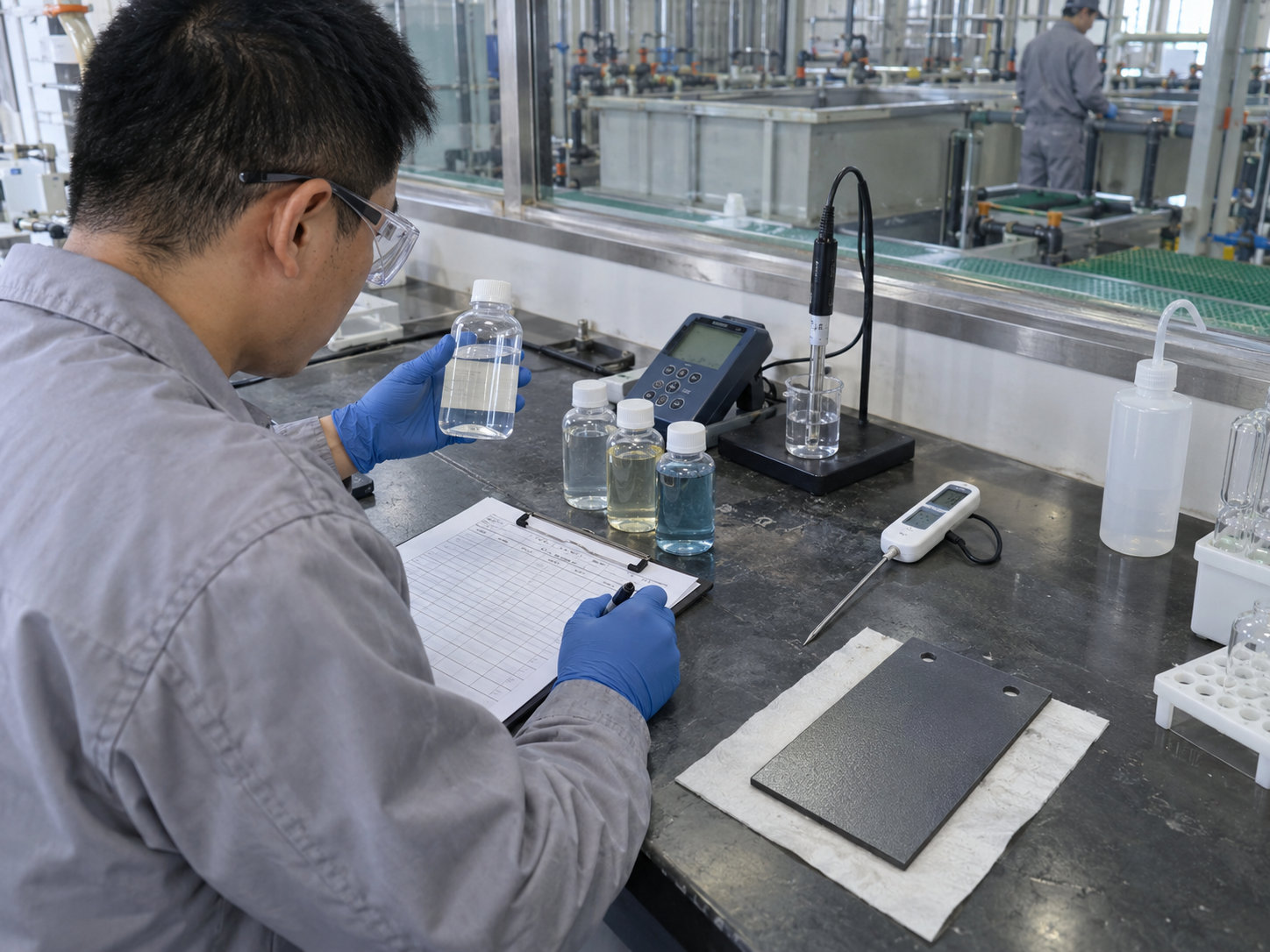
Laboratory analysis of electrolysis product samples
Zone E

Process Result

  • Product concentration or removal rate
  • Energy use per unit of output
  • Stability over the agreed run time
Checked by: ____Date: ____
Technicians servicing an electrolytic cell stack
Zone F

Maintenance

  • Electrode removal and refit time
  • Cleaning access and procedure trial
  • Spare part list and identification
Checked by: ____Date: ____

Want this checklist prepared for your project before the sample ships?

Request My Acceptance Checklist →
Quality Passport

A Single Quality Passport for Every Cell and Every Batch

Each cell leaves our factory with one document tying the electrodes, body and interfaces back to the drawing you approved. When you reorder a year later, we build to the same record, and your incoming inspection takes minutes instead of days.

Cell Quality Passport
DOC: ARY-QP-ECDRAWING REV: __BATCH: __
Laser marking a serial number on a titanium electrode partPart identity marking
Coordinate measuring of electrode flatness and dimensionsDimension and flatness check
TIG welding titanium mesh electrode to a conductorWelding and connection record
Field 01

Approved Drawing and Revision

The exact revision built, so every repeat order matches the cell you validated.

Field 02

Electrode and Titanium Part Identity

Substrate grade, coating type and part marking traceable to the coating batch.

Field 03

Dimensions, Chambers, Interfaces, Flatness

Critical dimensions measured against the drawing, including port positions and plate flatness.

Field 04

Welding, Connections and Assembly

Weld and terminal checks plus assembly notes, cutting the risk of hot spots at contacts.

Field 05

Applicable Checks and Packaging

Only the checks agreed for your cell, plus packing photos taken before the crate is closed.

Field 06

Sample and Production Batch Reference

Links each production batch to the approved sample, making deviations easy to trace.

Approved sampleSample ref: S-____
same drawing → same record →
Production batchBatch ref: P-____

Ask for a blank passport template to review with your quality team.

Get the Passport Template →
Manufacturing Evidence

See Where Your Electrodes and Cells Are Made, Checked and Packed

Before you shortlist a supplier, you need proof the work happens in-house. These are the steps your parts pass through at our factory in Foshan, China, from titanium fabrication to export crating.

ARY Titanium engineers reviewing electrode drawings and samples

Team and Company Facts

One team handles R&D, coating, fabrication and export, so your questions reach the people building your parts.

~100 employeesOEM / ODMSamples 1–10 pcs
Laser cutting titanium sheet for electrode fabrication

Titanium Fabrication

Cutting, forming and coating under one roof.

Workers welding and assembling an electrolytic cell frame

Welding and Assembly

Connections and interfaces built to drawing.

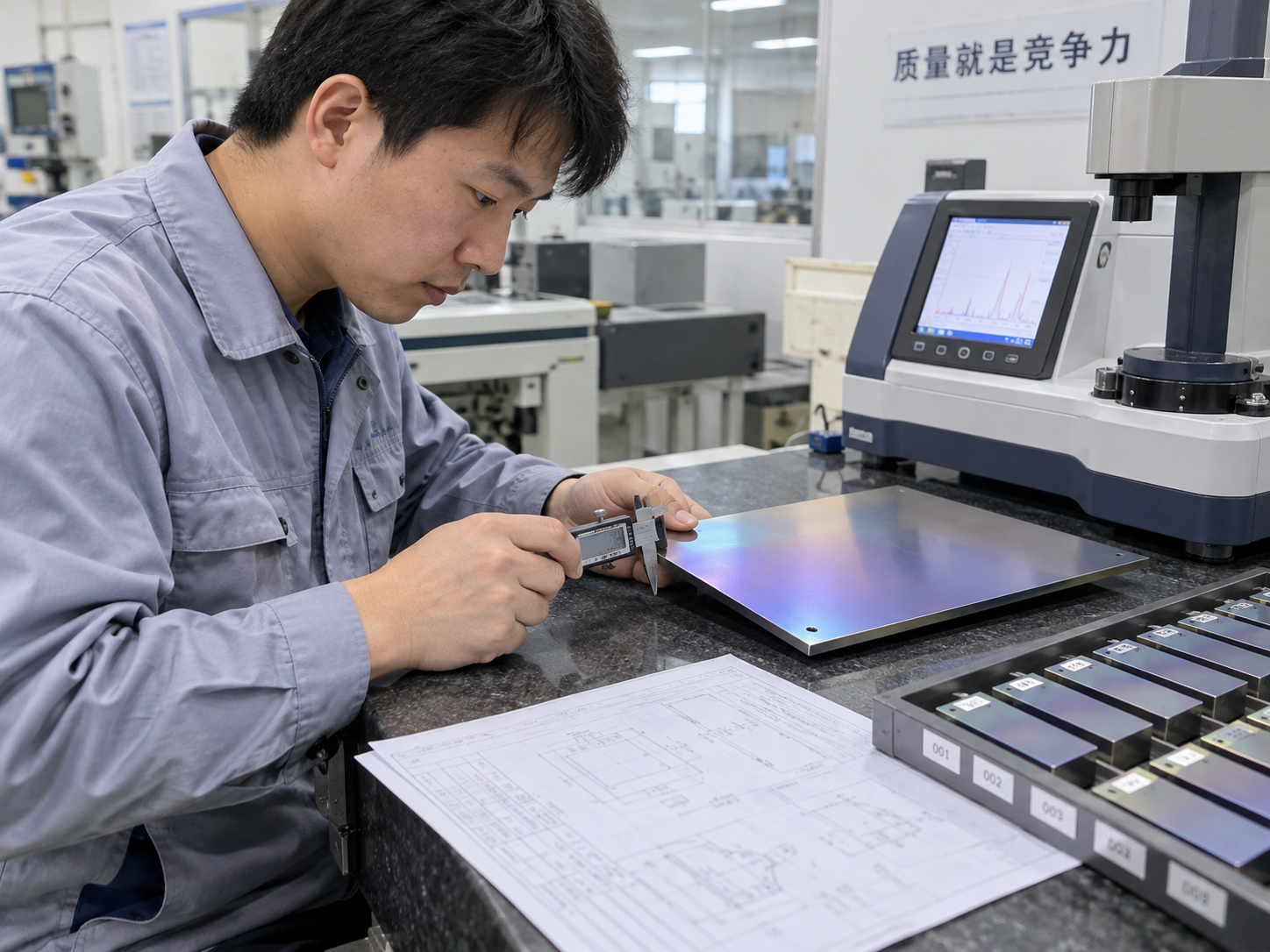
Inspector measuring a coated titanium electrode

Inspection and ID

Measured, marked and recorded per batch.

Export wooden crates with titanium electrodes ready for shipment

Export Packaging

Plywood cases, edge protection, steel straps.

Engineers reviewing a confidential customer drawing

NDA, Drawing Protection and Export Support

NDA signed on request before drawings are shared, restricted file access, and export documents prepared for your customs broker.

Shipped to customers in:United StatesGermanyUnited KingdomIndiaAustraliaUAESaudi Arabia

What Engineering Buyers Tell Us

"They came back with a list of eight missing data points before quoting. Answering them up front meant the sample cell matched our hypochlorite target on the first test."

PE
Process EngineerWater treatment OEM · Germany

"We switched from lead anodes in our electrowinning line. The titanium anodes arrived with batch records tied to the drawing, which made our incoming inspection simple."

PM
Plant ManagerMetal recovery · Australia

"Ports, terminals and mounting holes were all on the approved drawing. The cell dropped into our existing skid without any modification on site."

ME
Mechanical LeadElectrolysis equipment builder · United States

"Small sample quantities let us run a pilot before committing budget. The repeat order a year later matched the sample exactly."

PB
Purchasing ManagerIndustrial chemicals · UAE

Want to see your parts on this production line? Ask for a video factory tour.

Book a Video Factory Tour →
Engineering Resource Shelf

Engineering Guides From an Electrolytic Cell Titanium Electrode Supplier

Six shelves of practical guidance on custom electrolytic cells, electrolysis electrode selection and titanium electrode care. Use them to prepare your data, brief your team and ask suppliers sharper questions.

Chemist preparing an electrolyte sample for testing
Process

Defining the Target Reaction

  • Writing a process goal a supplier can quote
  • Electrolyte data that changes coating choice
Request this guide →
Coated titanium mesh electrode with conductor rod
Electrodes

Electrode Selection and Spacing

  • MMO, Ir-Ta or Pt: matching coating to reaction
  • Plate, mesh or tube, and how gap affects voltage
Request this guide →
Stainless electrolysis cell cabinet with flow piping
Flow

Cell Flow and Chamber Arrangement

  • Single-pass versus recirculating designs
  • Divided and undivided chamber layouts
Request this guide →
Electrolytic test cell with busbar connections and oscilloscope
Electrical

Current, Voltage and Connections

  • From total amps to current density per plate
  • Sizing terminals and avoiding contact heating
Request this guide →
Electrolysis system with gas and heat monitoring instruments
Gas and Heat

Gas, Heat and Monitoring Interfaces

  • Hydrogen venting and gas separation basics
  • Where to place temperature and level sensors
Request this guide →
Engineer testing a titanium electrode sample after service
Maintenance

Cleaning, Installation and Failure Analysis

  • Acid cleaning without damaging the coating
  • Reading a failed titanium electrode
Request this guide →

Frequently Asked Questions

Quick answers to what engineers and buyers ask most before ordering a custom electrolytic cell.

01What information do you need to quote a custom electrolytic cell?
Electrolyte composition, flow rate, temperature range, current or current density, voltage limit, expected gas and your output target, plus a drawing or sketch and quantity. If some data is missing, we send a short gap list instead of guessing, so your quotation reflects your real process.
02Can you supply only the titanium electrodes for my existing cell?
Yes. We are a titanium electrode manufacturer first. Send the drawing or the old electrode, and we match the dimensions, terminals and spacing so the new electrodes fit your current cell body without modification.
03Which coating should I choose: MMO, Ir-Ta or platinum?
It depends on the reaction. Ru-Ir MMO suits chlorine evolution in brine and seawater, Ir-Ta suits oxygen evolution in acidic electrolytes, and platinum suits low-current or special-purpose duties. We recommend a coating after reviewing your electrolyte and current density.
04What is your minimum order quantity?
Samples start from 1–10 pieces, so you can validate performance before committing budget. After approval we move to a pilot batch, then volume production on the same frozen drawing and quality record.
05How long does a sample take?
Standard electrode samples typically ship within 5–7 working days, and custom electrode prototypes within 10–14 days. Complete cells depend on body material and interfaces, so we confirm a firm lead time with your quotation.
06Can worn electrodes be recoated?
In many cases, yes. If the titanium substrate is not pitted or deformed, we can strip and recoat it, which usually costs less than a new electrode. Send photos or a used part and we will assess it.
07How do you protect my drawings and process data?
We sign an NDA on request before you share sensitive files, restrict drawing access to the project team, and never reuse your design for other customers.
08How are cells and electrodes packed for export?
Parts are protected individually and packed in export plywood cases with edge protectors and steel straps. We have shipped to customers in the United States, Germany, the UK, India, Australia, the UAE and Saudi Arabia.

Still have a question about your cell? Ask our engineers directly.

Ask an Engineer →
Cell Design Brief

Build Your Cell Design Brief in Five Short Steps

Share what you know today. Our engineers turn it into a structured brief, mark what is missing and reply with a design direction you can take to your team, without committing to an order.

ARY engineers reviewing a customer cell design brief on a tablet
  • Gap review: we list missing data so quotes are compared on equal terms.
  • Design direction: coating, electrode layout and cell concept for your process.
  • Confidential: NDA available before you upload drawings.

Prefer to start with a drawing only? Jump straight to the upload step.

Or email inquiry@titanium-anode.com

Step 1 · Company, Application and Process Goal

Tell us who you are and what the cell must achieve.

Step 2 · Electrolyte, Reaction, Flow and Output

Approximate values are fine. We will flag anything critical.

Step 3 · Electrodes, Electrical, Gas and Thermal Data

These values decide coating choice, conductor size and venting.

Step 4 · Cell Geometry, Interfaces and Maintenance

Help us fit the cell into your system on the first attempt.

Step 5 · Drawings, Validation, Quantity, Delivery and NDA

Attach what you have. Sketches and photos are welcome.

Your brief goes straight to an engineer, not a sales queue.

Your Cell Design Brief

Company
Not provided yet
Application
Not provided yet
Process goal
Not provided yet
Electrolyte
Not provided yet
Current
Not provided yet
Coating
Not provided yet
Quantity
Not provided yet