
Specify Titanium electrode connections by current, joint design, exposed materials, mechanical loads, and inspection requirements. Your cell draws expected current, yet one tab runs hotter and the assembly loses voltage. Replacing the coating will not resolve a resistive joint or poorly supported connection. Review the complete path from rectifier terminal to active surface before freezing a drawing.
1. What Must a Titanium electrode Connection Carry?

A Titanium electrode connection must carry electrical current and expected mechanical loads while remaining compatible with its environment. Continuous current, startup peaks, and vibration can create different design demands.
What belongs in the connection specification?
Trace the complete path from supply to surface. Include cables, busbars, joints, tabs, welds, and active regions. A missing interface can become the hottest point in an otherwise sound assembly.
- State continuous and peak current.
- Mark wet, splash, vapor, and dry zones.
- Describe support loads and movement.
| Check | Decision |
|---|---|
| Electrical duty | Sets current and loss requirements |
| Mechanical duty | Sets support and joint requirements |
A connection specification must describe more than hole diameter. Key Takeaway: Review electrical and mechanical duties together.
2. Why Can a Titanium electrode Joint Run Hot?

A Titanium electrode joint can run hot because contact resistance converts electrical power into heat. Loose, contaminated, misaligned, or undersized interfaces deserve investigation.
How does current affect heating?
Measure the joint rather than guessing from appearance. For an ohmic connection, power loss follows P = I²R. Doubling current multiplies resistive heating by four when resistance remains unchanged.
- Inspect contact condition and alignment.
- Measure voltage drop using an approved procedure.
- Compare temperature under matched operating duty.
| Check | Decision |
|---|---|
| Current increase | Raises resistive heating strongly |
| Contact resistance increase | Adds loss at the same current |
A small connection resistance can matter at industrial current. Key Takeaway: Investigate hot joints before raising the rectifier setting.
3. Where Should a Titanium electrode Contact Stay Dry?
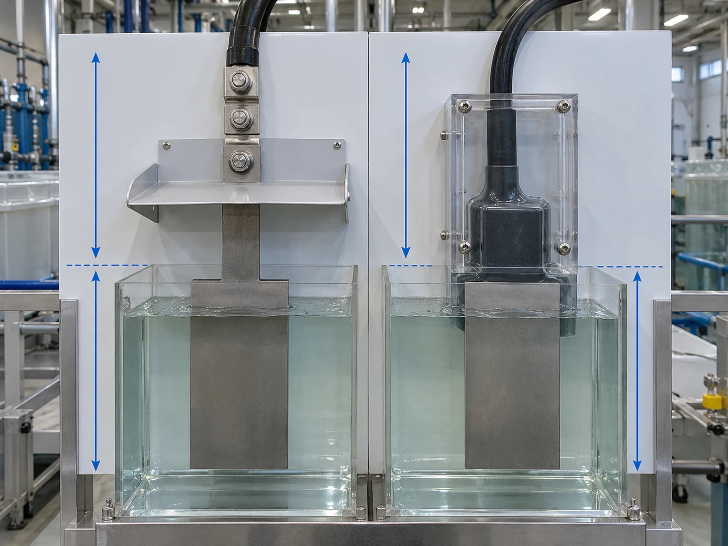
A Titanium electrode contact should remain dry when its material and joint design are intended only for a dry connection zone. Splash and vapor exposure need explicit consideration even above liquid level.
How should the drawing show exposure?
Mark more than the nominal waterline. An assembly may experience filling, sloshing, condensation, or cleaning liquid. Place joints and barriers according to those actual conditions.
- Show maximum liquid and splash boundaries.
- Identify vulnerable metals and interfaces.
- Provide drainage and inspection access where needed.
| Check | Decision |
|---|---|
| Dry-rated joint | Keep outside its prohibited exposure |
| Wetted joint | Requires compatible materials and design |
A nominally dry tab can become a wet connection during maintenance. Key Takeaway: Design the exposure boundary around operating and cleaning conditions.
4. How Do You Size a Titanium electrode Tab?

Size a Titanium electrode tab using current, path length, thermal behavior, allowable loss, and mechanical requirements. A universal tab width cannot cover different duty and mounting conditions.
Which inputs should the fabricator receive?
Send the current path and the support arrangement. A custom fabrication review can evaluate proposed tab geometry against those inputs. Avoid reducing the section at a hole or weld without checking its effect.
- State tab length and available contact footprint.
- Identify holes, bends, and local reductions.
- Define temperature and voltage-drop criteria.
| Check | Decision |
|---|---|
| Electrical cross-section | Affects resistance and heat |
| Mechanical section | Carries clamp and handling loads |
A generous-looking tab may still have a narrow local bottleneck. Key Takeaway: Qualify the final tab geometry in its installed configuration.
5. Should a Titanium electrode Use Welded or Bolted Joints?
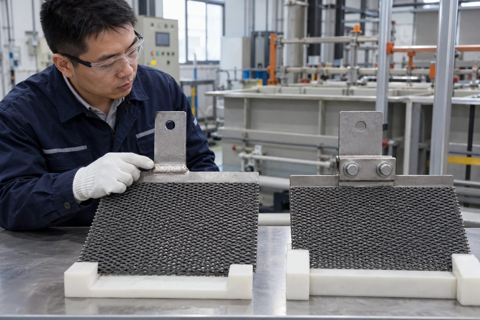
A Titanium electrode can use welded or bolted joints when the chosen design meets electrical, mechanical, and environmental requirements. Access for service and inspection often determines the practical choice.
What trade-offs belong in the review?
Compare the lifecycle of the joint. A removable connection helps maintenance but needs controlled contact preparation and tightening. A welded connection requires a suitable fabrication process and inspection.
- Check whether routine removal is required.
- Define mating materials and surface condition.
- Agree fabrication sequence before coating.
| Check | Decision |
|---|---|
| Bolted joint | Allows removal with controlled assembly |
| Welded joint | Provides a permanent fabricated interface |
Neither joint type is automatically suitable without a defined process. Key Takeaway: Choose the joint around service access and qualified fabrication.
6. Can You Weld a Finished Titanium electrode?

Welding a finished Titanium electrode requires supplier review because heat and handling may affect coating, geometry, and joint condition. Field modification should not be treated as equivalent to the approved fabrication process.
What should a change request include?
Resolve the sequence before production. Specify weld location, coated boundaries, heat-affected regions, and inspection needs. Where practical, complete qualified fabrication before applying the active coating.
- Identify the exact part revision.
- Mark proposed welding and protection areas.
- Request post-modification inspection and test criteria.
| Check | Decision |
|---|---|
| Planned fabrication | Can be qualified before coating |
| Finished-part modification | Needs a specific engineering disposition |
A mechanically sound-looking weld does not prove nearby coating remains qualified. Key Takeaway: Obtain a documented modification plan before welding a coated part.
7. How Do You Control Titanium electrode Contact Assembly?

Control Titanium electrode contact assembly through specified surfaces, fasteners, alignment, and tightening methods. Excessive clamp force can distort a tab while insufficient force can impair contact.
What should the work instruction specify?
Use the joint designer's assembly values. A torque figure copied from another material or bolt size can be misleading. Define the actual fastener condition and inspection method.
- Identify fastener materials and any approved interface treatment.
- Keep active coating out of unintended contact zones.
- Record assembly and reinspection requirements.
| Check | Decision |
|---|---|
| Correct assembly procedure | Supports repeatable contact |
| Uncontrolled tightening | Can cause loss or damage |
Torque alone cannot describe joint quality without material and surface conditions. Key Takeaway: Use one controlled work instruction for each joint design.
8. How Does Polarity Affect Titanium electrode Connections?

Titanium electrode polarity markings help prevent incorrect wiring and support approved reverse-duty operation where designed. Terminal identity must remain clear after maintenance and replacement.
Which markings should survive service?
Verify polarity at the actual terminal. For hypochlorite system duty, the coating and controller must match the intended duty. Use durable part and terminal identification that technicians can read after assembly.
- Show polarity on drawings and wiring schedules.
- Identify reversible and fixed-polarity circuits.
- Recheck after rewiring or controller work.
| Check | Decision |
|---|---|
| Terminal identification | Reduces wiring ambiguity |
| Electrical verification | Confirms the actual connection |
A correct label cannot prove that upstream wiring is correct. Key Takeaway: Combine durable identification with a defined commissioning check.
9. How Should You Inspect Titanium electrode Connections?

Inspect Titanium electrode connections for dimensions, joint condition, continuity, and operating loss where applicable. A visual check alone may miss a resistive interface.
Which tests fit a release plan?
Use measurements tied to the joint's function. An appropriate low-resistance method can support factory checks, while a controlled operating test reveals heating and voltage loss. Define instrument setup and acceptance limits.
- Check weld and contact condition.
- Confirm tab position and hole alignment.
- Record test current, temperature, and measurement locations.
| Check | Decision |
|---|---|
| Dimensional inspection | Confirms mating fit |
| Electrical inspection | Checks the intended current path |
A test report needs enough detail for another technician to reproduce it. Key Takeaway: Approve connection evidence alongside coating evidence.
10. What Titanium electrode Connection Details Should You Send?

Send Titanium electrode current duty, tab drawing, mating busbar details, exposure zones, and support arrangement for review. Those details make a connection proposal specific to your cell.
How can we support the drawing review?
Include the mating parts in the package. We can review custom electrode fabrication and connection requirements with your engineering team; contact us today with the assembly drawing. Our position is that connection quality belongs in the electrode specification from the start.
- Attach busbar and cable interface dimensions.
- State loss, heating, and service-access criteria.
- List inspection and sample-assembly requirements.
| Check | Decision |
|---|---|
| Part drawing | Defines the electrode interface |
| Assembly drawing | Shows its real operating context |
A complete interface package reduces changes after coating and delivery. Key Takeaway: Approve the joint and electrode as one working assembly.
Frequently Asked Questions
Can I use the same tab for a higher-current model? Only after review. Current, resistance, heating, and mechanical loads may require a different design.
What's the best connection material? It depends on electrical and exposure requirements. Dry, splash, and wetted interfaces may need different solutions.
How do I know if a joint is causing voltage loss? Measure across the joint using an approved method under known conditions. Compare the result with its acceptance criterion.
Can I tighten a hot connection while equipment runs? Use the site's isolation and maintenance procedure. A hot joint needs diagnosis and controlled correction.
Can I weld a new tab onto a coated electrode? Only with an approved modification plan. Heat, geometry, coating condition, and post-work verification must be addressed.